✅ Winch Solenoid — Wiring, Testing, Bypass
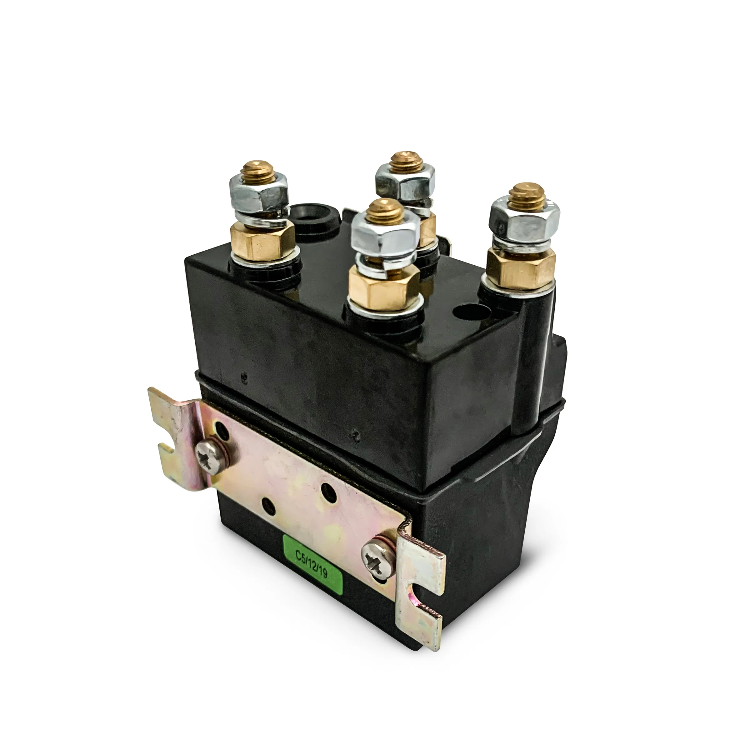
- Solenoid pack switches high-current motor power from a low-current remote trigger. 4 solenoids control forward/reverse polarity.
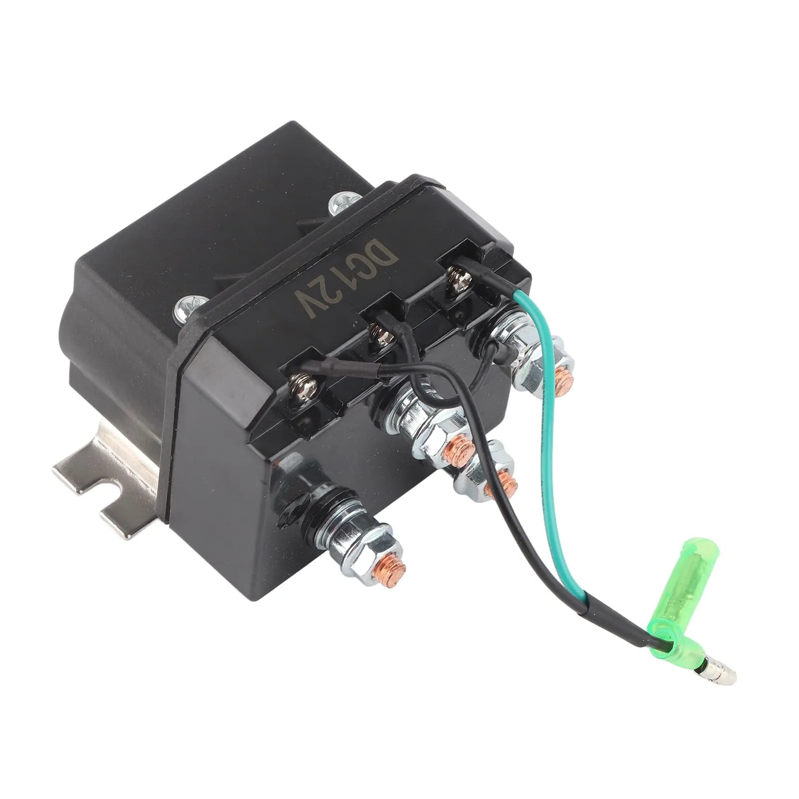
- Modern contactor (Albright SW180, Warn Zeon integrated) is a single sealed unit, more reliable than a 4-solenoid pack.
- Common failures: stuck-on (motor runs without trigger), burnt contacts (clicks but no motor), coil burnout (no click at all).
- Test with a multimeter: 12V across coil → should hear click, continuity across high-current contacts should drop to <0.05Ω.
- Bypass for troubleshooting only: direct 12V to motor terminal runs motor at full speed — never use as a permanent fix.
Key Takeaways
- A winch solenoid is a high‑current relay that connects the battery to the winch motor and reverses motor polarity to give you in/out control from a low‑amp switch.
- 2-solenoid systems are simple and cheap but not as flexible or robust. 4-solenoid packs share current across more contacts and handle direction changes more gracefully.
- A contactor is a sealed, heavy‑duty multi‑pole relay that replaces a traditional solenoid pack and usually gives better reliability, higher current capacity, and cleaner wiring.
- You can bypass a winch solenoid by wiring the motor straight to the battery, but that’s a last‑resort, trail‑only move because it’s easy to overheat stuff or lose control.
- Testing a solenoid correctly means checking coil resistance, continuity through the contacts, and voltage drop under load with a multimeter, not just listening for the click.
- “Click but no movement” usually comes from voltage drop, burned contacts, weak batteries, or crusty connections. The solenoid might not be the only culprit.
- Replacement solenoid packs typically run about $50–$200. A high‑end Albright‑style contactor will often be $300+, but you gain durability and better sealing.
- Good weatherproof housings, proper wire gauge, and sealed connectors are the difference between a reliable winch and one that fails the first wet winter.
What Is a Winch Solenoid? (Quick Definition)
 What is a winch solenoid? A winch solenoid is an electromagnetic switch that lets your low‑current control signal from a remote, dash switch, or wireless receiver turn a very high current on and off between the battery and the winch motor. Several solenoids (or a single multi‑pole contactor) are arranged so that energizing different coils reverses motor polarity, which is what gives you “in” and “out.” In a traditional solenoid pack, each individual solenoid is its own small relay and they’re wired together to create the correct paths for power. A contactor does the same job but bundles multiple poles into one compact, sealed housing with higher current ratings and fewer exposed joints.
What Is a Winch Solenoid? (Solenoid vs Contactor — Key Difference)
 A winch solenoid is an electromagnetically actuated relay. Your control switch feeds a small current into the solenoid coil. That coil builds a magnetic field, pulls a plunger, and slams a set of heavy copper contacts together. Those contacts are what connect the battery to the winch motor or change which way the current flows, so the drum spins the right direction. On most electric recovery winches, two or four of these solenoids live together in a plastic or metal solenoid pack, usually on top of the winch or under the hood. That pack is what actually routes the serious power. If the pack fails, the winch is just a paperweight, no matter how fancy the motor is.
Winch Solenoid vs Contactor – Key Difference
Both solenoids and contactors switch big current, but they’re laid out differently and behave a bit different in the real world.- Winch solenoid (pack)
- Made from a set of individual relays, usually 2 or 4, each handling part of the circuit.
- Each unit is typically single pole, single throw (SPST), so you wire several together to get forward and reverse.
- Very common on older and mid‑range winches, including many classic Warn solenoid and Smittybilt solenoid packs.
- Lots of exposed studs, bus bars, and short jumpers. More things to corrode or loosen over time.
- Contactor
- One sealed block that contains multiple internal contacts and coils in a single assembly.
- Usually rated for higher continuous and peak currents than cheap individual solenoids.
- Often uses a double‑pole, double‑throw (DPDT) or similar layout internally to flip polarity without a mess of external wiring.
- Common examples: Albright contactor, Gigavac contactor, and other sealed industrial units.
- Very good sealing, fewer external bolts and jumpers, usually more reliable under mud, water, and salt.
How Winch Solenoids Work: 2-Solenoid vs 4-Solenoid Systems
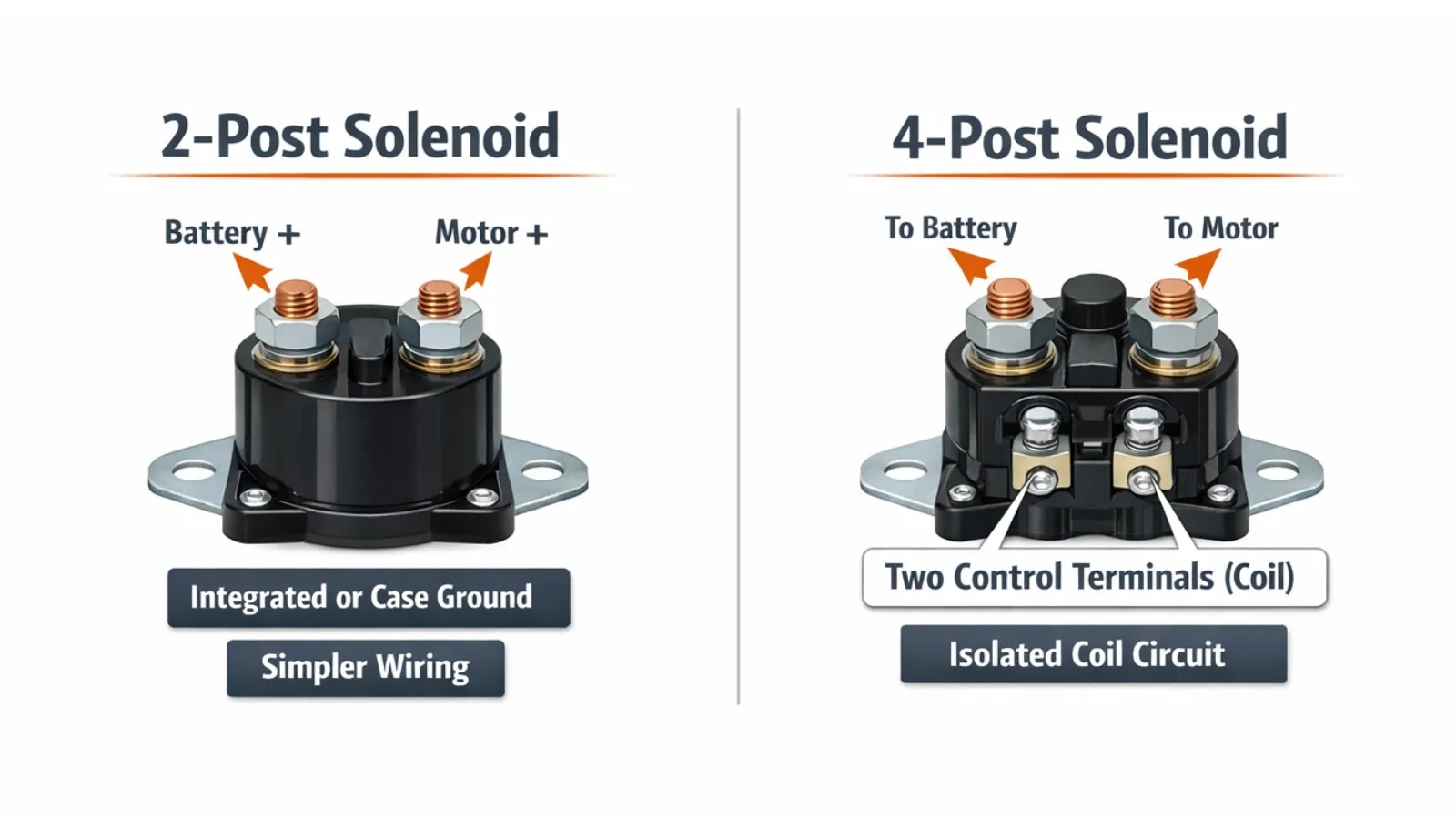 The whole trick to an electric winch is reversing the polarity at the motor. On a 12V permanent‑magnet or series‑wound DC motor, if you feed positive to one terminal and negative to the other, it spins one way. Swap them, it spins the other way. That’s all your “in” and “out” control is doing. To pull that off cleanly, most winches use either a 2-solenoid setup or a 4-solenoid setup, or they use a contactor that mimics a 4‑solenoid H‑bridge inside a sealed case.
- 2-solenoid system: Minimal hardware, often with shared grounds or factory links inside the motor. Works, but not as forgiving under heavy abuse.
- 4-solenoid system: Each side of the motor gets its own high and low switching path. More control, better current distribution, and nicer failure modes.
2-Solenoid Systems – Basic Operation
In a basic 2‑solenoid system, you’re relying on a pretty simple layout that many budget winches use.- Battery positive (+) is tied into both solenoids on a common feed stud or bus bar.
- The motor terminals A and F (or A1/A2, F1/F2 depending on your motor) are what the solenoids send power to.
- The negative side is usually a shared ground reference, either through the case, through a cable, or through an internal jumper in the motor.
4-Solenoid Systems – Why Many Winches Use Them
A 4-solenoid configuration spreads the job across four smaller relays so each one carries less load and you can build a proper H‑bridge. This is what you’ll see on a lot of better Warn setups and higher‑quality imports.- Solenoid count: 4 individual units arranged in two pairs.
- Current per solenoid: typically 150–250 A each on common setups, sometimes more on premium parts.
- Combined path resistance: kept very low, often below 0.1 ohm, to avoid throwing away power as heat.
- Motor polarity reversal: achieved by energizing opposite solenoid pairs to reverse which side is positive and which is grounded.
- Shares current so no single contact has to carry the entire punch alone.
- Cuts down on contact wear and arcing per solenoid.
- Often lets you limp along if one relay starts getting flaky, instead of leaving you totally dead.
Complete Winch Solenoid Wiring Guide
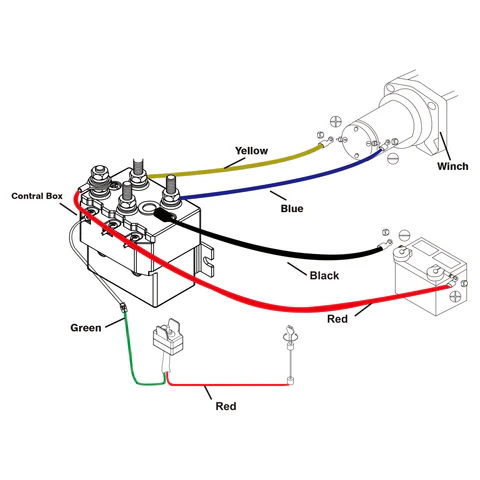 Good winch wiring is what separates a reliable recovery setup from a bonfire waiting to happen. Here we’ll walk through how a 2-solenoid wiring diagram, a 4-solenoid wiring diagram, and a contactor wiring layout usually look, with the focus on the solenoid pack and motor side of the system. Vehicle‑side routing, fusing, and mounting is its own subject. If you’re doing a fresh install, cross‑check with our solenoid installation during setup guide so you don’t miss the bigger picture.
Wire Colour Coding Basics
Colour codes are only “standard” until you open the box and find something different. Still, there are common patterns most brands follow:- Red – main battery +12V (BATT+) or the feed into the solenoid common stud.
- Black – battery negative (BATT–), motor ground, or ground straps.
- Green / Yellow – control signal wires for IN and OUT from the hand controller or dash switch.
- Blue / Brown – extra control circuits such as wireless receivers or in‑cab switches.
2-Solenoid Wiring Diagram
On a typical 2‑solenoid system, the diagram is straightforward once you stare at it for a minute.- A big battery +12V cable feeds a common stud or bus that both solenoids share.
- Each solenoid’s output stud runs to one motor terminal, often labeled M1 and M2, or A and F.
- The remaining motor terminals or the case are tied into ground, either through a cable straight to the battery or via the chassis.
- Each solenoid has small coil terminals that get power from the control switch when you hit IN or OUT.
Battery + ----(large red)----[COMMON STUD S1 & S2]

S1 OUTPUT ----(large cable)---- Motor Terminal 1 (M1)
S2 OUTPUT ----(large cable)---- Motor Terminal 2 (M2)

Motor case / other motor terminals ----(large black)---- Battery -

Switch "IN" ----(small wire)---- S1 COIL +
Switch "OUT" ----(small wire)---- S2 COIL +
Coil - typically grounded
Three big points people miss:
- Use the right wire gauge. For a decent‑sized winch, 2 AWG is bare minimum. Many heavy 10–12k setups are happier on 1/0 or 2/0, especially with longer runs.
- Crimp your ring lugs properly, torque the nuts, then cover everything with heat shrink and a little dielectric grease. Loose or dirty studs cook solenoids.
- Keep cables away from sharp brackets, moving steering parts, and exhaust components. A rubbed‑through positive cable will ruin your day fast.
4-Solenoid Wiring Diagram
On a 4-solenoid wiring diagram, you’re building that H‑bridge we talked about earlier. It looks complicated the first time, but once you understand which pair is “IN” and which pair is “OUT,” it clicks.- Two solenoids live on the high side, connecting battery + to the motor terminals when energized.
- Two live on the low side, connecting the motor terminals to ground when they close.
- The coils are wired so one diagonal pair gives IN, the other diagonal pair gives OUT.
 S1 (HIGH +) S2 (HIGH +)
Battery+ ---/ /---- M1 Battery+ ---/ /---- M2

 S3 (LOW -) S4 (LOW -)
M1 ---/ /---- Battery- M2 ---/ /---- Battery-
Control logic looks like this:
- IN: S1 and S4 energized → M1 sees +12V, M2 is pulled to ground.
- OUT: S2 and S3 energized → M1 is grounded, M2 sees +12V.
- Solenoid count: 4, obviously.
- Current per solenoid: often 150–500 A peak rating, though real‑world continuous numbers are lower.
- Combined winding resistance: kept very low so you don’t throw away voltage inside the pack.
- Motor polarity reversal: happens automatically from the opposite high/low pairing you energize.
Contactor Wiring (Premium Setup)
Swapping to a contactor like an Albright contactor or Gigavac contactor is one of the best upgrades you can do for an older 4‑solenoid winch. You keep the same basic logic but ditch four separate cans for a single, sealed block. Most decent contactors share similar specs and layout:- Continuous current rating: often 250–500 A. Match it to your winch rating and how hard you run it.
- Peak current capacity: easily 1000+ A for a few seconds, which covers most stall conditions.
- Coil voltage: 12V on most rigs, 24V on some bigger trucks and military surplus winches.
- Contact configuration: DPDT or a functionally equivalent multi‑pole H‑bridge inside the case.
- Big studs for BATT+ and BATT– or a chassis ground point.
- Big studs for the motor terminals, normally M1 and M2 or similar labels.
- Several small control posts:
- One for the IN coil + and one for the OUT coil +.
- Shared coil ground or individual grounds, depending on model.
Battery+ ----(large red)---- Contactor BATT+
Battery- ----(large black)---- Contactor BATT-

Contactor M1 ----(large cable)---- Motor Terminal 1
Contactor M2 ----(large cable)---- Motor Terminal 2

Switch "IN" ----(small wire)---- Contactor IN COIL +
Switch "OUT" ----(small wire)---- Contactor OUT COIL +
Coil - to ground
The nice part is you no longer have to build the H‑bridge out of four separate solenoids and jumper wires. The contactor handles that logic internally. For a closer look at how that compares on the electrical side, loop back to solenoid vs contactor.
Can You Wire a Winch Without a Solenoid? (Direct Wiring Method)
Yes, you can wire a winch motor directly to the battery and get it to pull with no solenoid pack. I’ve done it on the trail more than once to get someone out. But you treat this as an emergency-only workaround, not a build strategy. Some folks call it a direct wiring bypass, others call it bypass relay wiring if they throw in a generic heavy‑duty relay. Either way, you’re sidestepping the designed safety and control, so respect what you’re doing or things get smoky fast.When Is Bypassing Safe?
“Safe” is relative here. It’s only reasonable under a few conditions:- You’re in a genuine emergency recovery situation, like stuck in a dangerous spot or miles from help.
- You understand basic DC wiring and you’re comfortable working around batteries and high current.
- You keep pulls very short and watch for heat buildup at the motor and cables.
- You can disconnect the battery in a hurry if a cable welds itself to something it shouldn’t.
- Control method: you’re manually making and breaking high‑amp connections or using a crude on/off switch. There’s no fine control.
- Wire gauge requirement: you still need proper heavy cable, usually 2–0 AWG, since the winch doesn’t pull any less current just because you’re bypassing the solenoid.
- Fuse rating: still have a serious fuse or breaker, often 300–500 A, to keep a dead short from becoming a fire.
- Safety limitation: you lose the normal safeguards and can’t just let off the switch and know everything’s dead and safe.
Step-by-Step Bypass Guide (Emergency Use)
Warning: This is not a beginner project. High‑current 12V systems can arc, start fires, and burn you pretty badly. If you’re not comfortable with that, get someone experienced to help.- Identify motor terminals.
- Most winch motors you’ll see on trucks have two main studs labeled something like M1 and M2, or A and F. Some older ones have extra field terminals.
- If you’re not sure which is which, stop and check the manual or the label stamped into the motor case.
- Disconnect the existing solenoid pack.
- Pull the battery + cable off the solenoid common stud so the pack is no longer live.
- Remove the motor leads from the solenoid outputs so you can run new cables without backfeeding anything.
- Make sure the old pack’s leads can’t accidentally touch power or ground.
- Prepare heavy cables.
- Use the correct wire gauge (AWG) for your winch. Often 2 AWG is the minimum, and bigger is better if the run is long.
- Install a big fuse or breaker rated around 300–500 A as close to the battery positive terminal as you can get it.
- Connect for single direction pull.
- Run Battery + (coming through your fuse) straight to Motor Terminal M1.
- Run Battery – either to Motor Terminal M2 or to the motor case/ground stud, depending on the design.
- This will give you one direction only. It can be “in” or it can be “out.” You’ll see on the test.
- Test briefly.
- Touch or clamp the Battery + lead to M1 for just a second and see which way the drum wants to turn.
- If the motor sounds angry or the cables jump, stop and double‑check your connections and fuse.
- To reverse direction (if absolutely needed):
- Disconnect both Battery + and – from the motor. Don’t swap while it’s live.
- Move the positive cable to the other terminal and the negative to the remaining one, so + to M2 and – to M1.
- Reconnect briefly to move the winch in the opposite direction. Keep pulls short.
- After recovery, revert wiring.
- Strip out the bypass and restore the normal configuration. This is a rescue move, not a permanent mod.
- Inspect the battery cables and motor lugs for heat damage. Replace the solenoid pack or upgrade to a contactor before the next big trip.
How to Test a Winch Solenoid (Step-by-Step)
Testing a winch solenoid the right way means you’re not just chasing the “click.” You’re measuring coil resistance, checking that the contacts actually close, and verifying voltage drop across the solenoid under load. You’ll need a half‑decent multimeter and space to access the solenoid pack safely.Solenoid Coil Basics (EAV Attributes)
Before you start poking around, it helps to know what a healthy coil looks like on paper.- Coil voltage: 12V on most 4×4 winches, 24V on some big trucks, tractors, and military gear.
- Coil resistance: usually somewhere around 3–30 ohms. The exact figure is in the manufacturer’s data, but that range is a good sanity check.
- Activation current: typically around 0.4–3 A when first energized at rated voltage.
- Holding current: slightly lower once the internal plunger has moved and the magnetic circuit is closed.
Step 1: Visual Inspection
Start with your eyes before you reach for the meter. You’ll be surprised how often the problem is obvious.- Look for melted housings, deformed plastic, or cracked cases. That screams overheating or impact damage.
- Check each stud and nut for green/white corrosion, rust, or blackened copper. That’s resistance and arcing.
- Grab the cable lugs and gently twist. If they spin on the stud, they aren’t tight enough and that alone can cause a voltage drop.
Step 2: Coil Ohm Resistance Test (Multimeter Test Procedure)
- Disconnect the winch power.
- Pull the negative battery cable off first and secure it so it can’t flop back onto the post.
- Find the small coil terminals on each solenoid. They’re the ones with thin wires, not the big battery and motor cables.
- Set your multimeter to the ohms (Ω) range.
- Place one probe on each coil terminal. If the coil uses the housing as ground, put one probe on the single small terminal and the other on clean bare metal on the case.
- Read the resistance:
- A healthy 12V coil usually measures in the 3–30 Ω range.
- Infinite/open or OL on the display means the wire inside the coil is broken.
- Near 0 Ω means the coil is shorted internally and will draw way too much current. Replace it.
Step 3: Bench Activation Test (Off‑Vehicle, If Possible)
- Pull the solenoid or the whole pack off the rig if you can get away with it. Bench testing is safer and easier.
- Use a known good 12V supply, either a battery or a regulated power supply, with an inline fuse.
- Clip +12V to one coil terminal and ground to the other (or to the case, depending on design).
- Pay attention:
- Hear a clean, firm click and feel the plunger snap inside the housing.
- No click, a weak buzz, or a sticky feel usually means the coil is bad or the mechanical bits are jammed with rust or debris.
Step 4: Continuity Test Across Contacts
- With the solenoid not energized:
- Measure resistance between the two big contact studs using the ohms range.
- See open circuit, basically infinite resistance.
- Energize the coil with 12V again, just like in the bench test.
- Measure across the big studs while the coil is powered:
- You want very low resistance, usually down below 0.05 Ω. Some meters won’t read that accurately, but it should be very close to a short.
- If it’s higher than that, the contacts are pitted, contaminated, or not closing fully and will get hot under load.
Step 5: Voltage Drop Across Solenoid (In‑Vehicle)
This is the real‑world test that separates a healthy “click” from a useless one. Many solenoids will still move but have burned contacts that choke current.- Reconnect the winch wiring and battery. Make sure the rope is tensioned safely and no one is near the drum or fairlead.
- If possible, start the vehicle so the alternator is supporting the battery.
- Put the multimeter on DC volts, not ohms.
- Stick the black probe on the input stud of the solenoid (coming from the battery) and the red probe on the output stud (going to the motor).
- Hit the winch IN or OUT to energize that solenoid while someone watches the meter.
- Watch the reading:
- A healthy solenoid will show a voltage drop under about 0.2–0.3V when pulling a decent load.
- If you see 0.5–1.0V or more, that solenoid is wasting power, getting hot, and starve‑feeding the motor.
Solenoid Fails — Click but No Movement: Diagnosis & Fix
“Solenoid clicks but no movement” is probably the number one complaint I hear. The click just tells you the coil is alive. It doesn’t guarantee that the contacts are carrying full current or that anything downstream is happy.Common Causes
- Low battery voltage or bad connections that collapse under load and drag the voltage way down.
- Corroded solenoid contacts creating resistance so the motor only sees a fraction of system voltage.
- Burned or welded contacts stuck in a half‑closed state, especially after heavy winching without cool‑down.
- Undersized or damaged cables, or cables with rotten crimps, causing huge voltage drop under load.
- Motor problems like stuck brushes, worn commutator, or internal shorts. See the motor guide at motor polarity and solenoid switching if voltage is present but the motor is dead.
Diagnosis Sequence
- Check the battery first.
- Measure voltage with the winch idle. A fully charged 12V battery should sit around 12.6–12.8V.
- Measure again while trying to winch:
- If it plummets under 10V, the battery or charging system is the starting point of your problem.
- Check all main power connections.
- Pull and clean battery posts, main ground straps, and every stud on the solenoid pack.
- Look for blackened insulation, heat‑stressed spots, or loose and crusty crimp lugs.
- Measure voltage at the motor terminals during a winch attempt.
- If you see no voltage at the motor but the solenoid clicks, the contacts are not closing properly or the wiring between solenoid and motor is open.
- If you do see voltage, but the motor doesn’t budge, you’re into motor internal issues or a jammed drum or gearbox.
- Perform the solenoid voltage drop test.
- As described earlier, a high voltage drop across any one solenoid means high contact resistance, which robs torque.
Repair vs Replacement Decision
Every solenoid has a limited life cycle rating. Every time it opens and closes under high load, a bit of metal burns off the contacts. Over time those silver‑alloy faces get pitted, oxidized, and out of shape.- Contact material: usually silver alloy over copper to handle arcing with lower resistance.
- Contact current rating: often in the 200–500 A continuous range, with much higher surge ratings during short pulls.
- Contact resistance: measured in milliohms. Even a small rise drives heat up dramatically under winch current.
When to Replace Your Winch Solenoid
Waiting until it completely dies is one way to find out your solenoid is done. The smarter move is to catch it before you’re buried in mud with no pull.End-of-Life Indicators
- No click at all on IN or OUT:
- That points to a dead coil, no control signal, or a blown fuse in the control circuit.
- Intermittent function:
- If you have to tap the housing, wiggle wires, or hit the switch three times to get it to engage, you’re likely dealing with worn contacts or corrosion inside.
- Burnt smell or visual discoloration:
- That’s usually overheated coils or contacts that have been arcing under heavy load.
- Excess heat in the solenoid pack compared to the power cables during normal winching.
- Cracks, water lines, rust or condensation inside what was supposed to be a sealed housing.
Cost: Replace Solenoid vs Upgrade to Contactor
- Solenoid replacement cost:
- Generic 2‑ or 4‑solenoid pack from a decent supplier usually lands between $50–$200 USD.
- Brand‑specific replacements, like an original Warn solenoid pack, tend to be up toward the top of that range.
- Contactor upgrade cost:
- A quality Albright contactor or Gigavac contactor setup with mounting bits is normally in the $300+ USD range.
- What you get for that is higher continuous current rating, much better sealing, smaller footprint, and often a better warranty.
Common Mistakes with Winch Solenoids (and How to Fix Them)
- Mistake 1: Undersized cables to the solenoid pack.
- Problem: The winch starves for voltage, cables get hot, and everyone blames the solenoid when the real choke point is skinny wire.
- Fix: Follow the manufacturer’s wire gauge recommendations. For most truck winches that means 2–0 AWG, short runs, clean crimps, and tight, protected lugs.
- Mistake 2: Mounting the solenoid pack where it floods or bakes.
- Problem: Solenoids sitting in the grille catching every puddle, or right above a hot manifold, fail early from water ingress and heat cycling.
- Fix: Relocate the solenoid pack or contactor higher and away from the exhaust path. Use weatherproof connectors, grommets, and sealed housings whenever possible.
- Mistake 3: Assuming “click but no movement” always means bad solenoid.
- Problem: People toss new solenoid packs at a problem caused by a dead battery, poor ground, or seized winch drum.
- Fix: Stick to a diagnostic sequence: battery health → cable and ground inspection → solenoid resistance and voltage drop → motor checks.
- Mistake 4: Running a bypass as a permanent setup.
- Problem: Direct wiring bypasses ignore safety and can overheat motors, melt insulation, and cause accidental operation.
- Fix: Treat bypass wiring as a short‑term trail fix only. Replace it with a proper solenoid pack or contactor as soon as you’re home.
- Mistake 5: Mixing 12V solenoid coils on a 24V system (or the other way around).
- Problem: Coils rated for 12V cook almost instantly on 24V. Coils rated for 24V may never pull in cleanly on 12V.
- Fix: Always match coil voltage (12V/24V) to your battery system and winch specs. Read the label on the solenoid or check the data sheet.
- Mistake 6: Never testing the winch until you’re stuck.
- Problem: You only find out the solenoid pack corroded over winter when you really need it.
- Fix: Exercise the winch every month or two under light load. Listen for weak clicks, feel for hot spots, and watch for slow or jerky movement.
FAQ
How does a winch solenoid differ from a contactor?
A winch solenoid pack strings several individual single‑pole relays together to switch battery power on and off and reverse motor polarity. A contactor, like an Albright contactor, is a single sealed multi‑pole relay that does all of that inside one housing with higher current ratings and better environmental protection. Both control the winch, but contactors are usually more compact, cleaner to wire, and more robust.How do I read a winch solenoid wiring diagram?
A winch solenoid wiring diagram shows how the battery, solenoid pack, motor terminals, and control switch are tied together. Thick lines indicate the high‑current paths like BATT+, BATT–, M1, and M2. Thin lines are the low‑amp coil control wires. On 4‑solenoid systems, look for that H‑bridge pattern where opposite pairs of solenoids are linked to give you IN or OUT when their coils are energized.How do I test a winch solenoid with a multimeter?
First, use the ohms range to measure coil resistance and make sure the coil isn’t open or shorted. Then energize the coil and check for continuity across the main contacts. Finally, measure voltage drop across the solenoid while the winch is pulling. A drop above roughly 0.3V under load points to high resistance or burned contacts that are choking current.Is it safe to bypass a winch solenoid?
Bypassing a solenoid by wiring the motor directly to the battery is only reasonable as a short‑term emergency measure. You lose normal safety protections, direction control is crude, and a wiring mistake can overheat cables or start a fire. As soon as you’re recovered, go back to a proper solenoid or contactor setup.What does it mean if the solenoid clicks but the winch doesn’t move?
If you hear a click but there’s no movement, the coil is pulling in, but full current isn’t making it to the motor. That can be low battery voltage, corroded or burned contacts, poor cable connections, or a bad motor. Don’t assume the solenoid pack alone is bad. Check voltage at the motor and perform the voltage drop tests before throwing parts at it.When should I replace my winch solenoid?
Replace the solenoid pack if it doesn’t click when commanded, only works sporadically, gives off a burnt smell, shows melted or cracked housing, or causes excessive voltage drop under load. Considering replacement solenoids are roughly $50–$200 and an upgraded contactor is around $300+, it’s usually cheaper to replace the pack early than deal with a ruined motor or failed recovery.Are all winch solenoids and contactors interchangeable?
No. Match the coil voltage (12V/24V), current ratings, and contact configuration to your winch motor and electrical system. Mounting holes, control plugs, and harness layouts vary by brand. Always verify compatibility with your specific winch model before you buy a replacement or upgrade.What’s the best winch solenoid or contactor for 2026?
For most drivers who just want their winch to work when needed, a quality OEM-style Warn or Smittybilt solenoid pack is the easiest drop‑in choice. If you winch heavy loads often, an Albright contactor or a similar Gigavac contactor gives you better sealing and current handling with fewer headaches, as long as you’re fine with a bit of wiring adaptation.Final Summary & Next Steps
The winch solenoid or contactor is the muscle behind your remote. It’s what turns that tiny button press into controlled power to the motor. Once you understand how 2- and 4-solenoid systems route power, how to read a winch solenoid wiring diagram, and how to use a multimeter for testing, you can wire, diagnose, and upgrade your setup with confidence instead of guesswork. Use bypass solenoid direct wiring only to get yourself out of trouble, then commit to fixing the system properly. A good contactor wiring upgrade or a solid solenoid pack isn’t just convenience, it’s peace of mind when you’re winching hard and far from home. For more detailed info and diagrams, check out:- solenoid vs contactor plus detailed motor polarity and solenoid switching discussions.
- solenoid testing along with full winch amp draw analysis.
- 4-solenoid diagram and solenoid installation during setup on new builds.
- solenoid wiring for truck‑specific layouts, fusing, and mounting tricks.
📖 Related deep-dive: The solenoid is one piece of a larger circuit — understand how it fits in the winch wiring overview.
📖 Related deep-dive: Ready to install? Follow the step-by-step: how to wire a winch solenoid.
📖 Related deep-dive: If the solenoid is dead and move the vehicle now, see the emergency guide: wiring a winch without a solenoid.
Part of the Winch Accessories guide. Explore more guides in this cluster for complete coverage.
🔧 Bench-Testing Solenoids Without A Winch
I keep a 12V deep-cycle + jumper test rig at the shop for solenoid diagnosis. Apply 12V to coil terminals, listen for click, then check continuity across the high-current contacts with a Fluke 87V in low-ohms mode. Good solenoid reads <0.05Ω closed. Burnt contacts read 0.3Ω+ — that’s enough to halve winch pulling power and overheat the unit. Replaced more than a dozen Warn-style solenoids this way over 5 years.