✅ Get The Pinout Right Or Nothing Works
- Standard winch rocker switches are momentary (ON)-OFF-(ON) DPDT — spring-return both directions. A regular maintained switch will leave the solenoid energized and cook the coil in about 3 minutes.
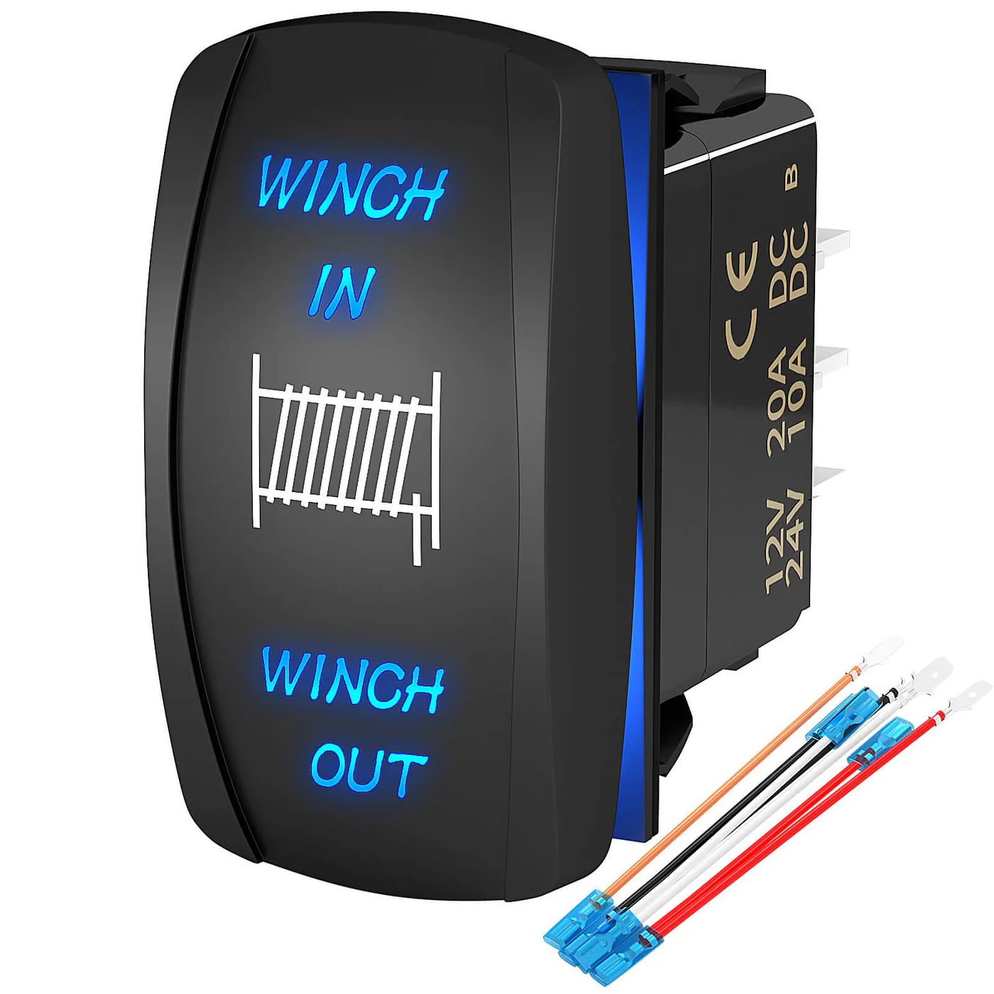
- 5-pin layout: power in, two coil outputs (F1/F2), and two ground/illumination pins. 7-pin adds a separate backlight circuit plus a common LED ground. Wire a 7-pin like a 5-pin and the LED won’t light.
- Circuit amp draw is tiny — under 1A — but the wiring matters because the switch is interrupting the trigger current to the solenoid coil, which can be 3–5A on older units. Use 16 AWG minimum, 14 AWG if you’re running over 10 ft.
- Inline fuse the switch feed at 7.5A. That protects against the coil-short failure mode where a dying solenoid pulls the switch circuit up to 15A.
- IP67 is the minimum rating for anything going on a dashboard or rollbar that sees weather. Carling Contura V is the industry baseline; Trombetta 114 and Warn 88996 are the OEM-style options.
Key Takeaways
- A winch rocker switch controls the solenoid with low-current 12V signals. The heavy current for the winch motor never passes through the switch.
- DPDT rocker switches are the right choice for full in/out winch control. SPST switches work best as a master on/off, ignition interlock, or safety lockout.
- Proper 3-wire winch switch wiring always includes a power feed, a ground or reference, and a control wire back to the solenoid pack or relay.
- Use an in-line fuse within about 6–12 inches of the battery or main feed, sized at roughly 1.25x the switch circuit’s expected current draw.
- For off-road, UTV, or recovery rigs, choose IP67 marine-grade or automotive-rated waterproof rocker switches and panels.
- Common mounting spots include dash panels, A‑pillar pods, overhead consoles, and sealed housings. Keep wiring away from sharp edges, hot exhaust, and moving parts.
- Frequent mistakes are undersized wire gauge, misidentified switch terminals, skipped grounds, and forgotten LED backlight wiring.
- Top picks for 2026 include Carling Technologies, ESUPPORT, Xislet, and Blue Sea Systems rocker switch panels for marine and open-cab rigs.
Quick Definition: What is a Winch Rocker Switch?
What is a winch rocker switch? A winch rocker switch is a dash-mounted, hand-operated electrical switch that sends control signals to the winch solenoid. Most proper winch rockers are momentary-contact DPDT switches that spring back to center and reverse polarity to safely run the winch in and out without feeding full motor current through the dash.
What is a Winch Rocker Switch? (How It Controls the Solenoid)
DPDT vs SPST: Which Switch Type for Winch Control?
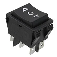
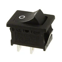 You mainly see two switch types in winch control systems: DPDT (double-pole double-throw) and SPST (single-pole single-throw). They look similar at a glance but they do very different jobs in a winch circuit. A DPDT winch switch can send two separate circuits to two different outputs and swap polarity. That is what lets one rocker handle winch-IN and winch-OUT from the same spot on your dash. An SPST switch just opens and closes a single circuit. It is great as a master power switch, safety lockout, or to turn backlighting on and off, but it will not reverse direction by itself. Short comparison: Use a DPDT rocker for full in/out winch direction control. Use an SPST rocker any time you just need to enable or disable the winch control circuit, add a safety arm switch, or manage an accessory like switch backlighting or a relay coil.
DPDT vs SPST Winch Switch Comparison
| Feature | DPDT Rocker Switch | SPST Rocker Switch |
|---|---|---|
| Poles | 2 (controls two separate circuits) | 1 (controls one circuit) |
| Throws | 2 (each pole can connect to two outputs) | 1 (on or off) |
| Typical winch use | Main IN/OUT control to solenoid | Master enable, ignition interlock, backlight power |
| Contact style | Often momentary (center-off) for in/out | Momentary or maintained for on/off |
| Wiring complexity | Higher (6 terminals common) | Lower (2–3 terminals) |
| 3-wire winch switch wiring | Common on DPDT center-off winch switches | Common on illuminated SPST (power, load, ground) |
| Best for | Full winch direction control from dash | Kill switch, safety lockout, accessory control |
Winch Rocker Switch Wiring: 3-Wire Diagram (Full Guide)
 A clean winch rocker switch wiring diagram protects your rig, keeps the solenoid happy, and saves you from mysterious no-click situations later. Different brands use different colors, but almost every 3-wire winch switch wiring layout follows the same logic.
- One wire brings fused 12V power into the switch.
- One wire carries the control signal back out to the solenoid control terminal or relay coil.
- One wire provides ground or reference, often shared with the switch LED backlight.
Wiring Diagram (Conceptual)
(Insert labeled wiring diagram image here in WordPress media) On paper, a basic 3-wire winch rocker switch wiring diagram for a 12V system looks like this:- Switch terminal 1 (Power in): Fused +12V from the battery or an ignition-controlled source if you want the winch disabled with the key off.
- Switch terminal 2 (Output/control): Signal wire that goes to the correct solenoid control post (IN or OUT) or to the coil of a relay in more complex harnesses.
- Switch terminal 3 (Ground/illumination): Solid ground for the switch body and LED backlighting, usually tied to chassis or battery negative.
Understanding Switch Terminal Labelling
One thing that trips people up is that rockers are not all labeled the same way. Some use numbers, some use letters, some have tiny symbols that are hard to see once the switch is in the dash.- COM or C: Common terminal. This is usually your power feed going in.
- NO: Normally Open. This terminal only connects to COM when the switch is turned on or pressed.
- NC: Normally Closed. This is connected to COM when the switch is at rest and opens when you operate it.
- L, LOAD, or OUT: Output terminal feeding your solenoid coil, relay coil, or accessory.
- ⊥ symbol: Ground terminal, often only for the LED backlight or indicator lamp.
Wire Gauge Selection for Winch Switch Circuits
Because the rocker circuit is low current, some folks get lazy and grab whatever skinny wire they find on the bench. That is how you end up with flickering LEDs, sticky solenoids, or insulation cooked near a heat source. Size it once and you are done. Typical winch switch circuits pull between 1–10 amps, depending on whether the switch is driving the solenoid coils directly or energizing an intermediate relay.- For runs under roughly 10 feet at up to 10A, 16 AWG automotive primary wire is usually fine.
- For longer runs, or where the wiring has to live near heat and vibration, bumping up to 14 AWG gives extra margin and tougher insulation.
- For off-road or marine rigs, go with stranded, tinned copper wire. It handles flexing better and resists corrosion far longer than bare copper in humid or salty conditions.
Step-By-Step Wiring Instructions
Here is a straightforward way to install a winch rocker switch with a 3-wire layout. Adapt the details to your exact switch and winch, but keep the order and safety steps.- Disconnect the battery Pull the negative battery terminal before you touch anything. Winch circuits are live, and even a quick slip can make a solenoid click or a cable jump when you are not expecting it.
- Plan your switch location Decide whether you want the rocker on the main dash, an A‑pillar pod, an overhead console, or in a Blue Sea Systems or similar accessory panel. Keep it where you can easily hit it with a gloved hand, but not where a knee, bag, or strap will bump it in rough terrain.
- Mount the switch Measure the switch body and cut the rectangular hole to suit. Standard automotive rockers are often around 1.45″ x 0.83″. Take your time on this cut so the switch snaps in snug and the panel does not crack. If you are using a marine-grade rocker switch panel, use the cutout template they provide.
- Run power feed wire
- From a fused 12V source, run your power wire to the back of the switch location. Many people go straight to the battery. Others tap an ignition-on circuit so the winch cannot run with the key off.
- Install an in-line fuse holder near the power source, not near the switch. That short stretch between the battery and the fuse is the only part that will not be protected.
- Connect switch power terminal Terminate the power feed with a proper crimp connector and slide it onto the switch’s COM/Power In terminal. Tug on the connector to be sure it is tight. Loose spades cause intermittent faults that are a nightmare to track down on the trail.
- Run control wire to solenoid Route a dedicated control wire from the rocker’s output terminal to the correct solenoid control stud as shown in your winch manual. On a DPDT IN/OUT setup you may have two outputs that each tie into a separate control wire at the solenoid. Label these wires at both ends so you can tell IN from OUT without guessing later.
- Connect ground / reference Find a clean, solid grounding point. Scrape paint if you have to and use a star washer. Run your switch ground terminal there or straight to battery negative. This ground often completes both the LED backlight circuit and the control circuit reference, so do not skip it.
- Secure and protect wiring Now dress the harness. Slip the wires into split loom or braided sleeve, add grommets where they pass through metal, and secure the bundle every foot or so with zip ties or clamps. Keep the harness away from exhaust pipes, sharp brackets, steering shafts, and pedals. A winch line snapping is bad enough. You do not want live wires rubbing through under your feet.
- Reconnect battery and test Reconnect the battery negative and get someone to watch the winch drum while you test:
- First check that any LED backlight or indicator works the way you expect.
- Then press IN and OUT with the winch unloaded. Hear the solenoid click cleanly in each direction.
- Hook the line to a light anchor, put a little tension on it, and confirm that IN pulls the cable onto the drum and OUT feeds it back off. Fix any reversed leads now, not on a muddy hill in the dark.
In-Line Fuse Sizing Guide
The in-line fuse in the rocker circuit is there to protect the wire, not the winch motor. People often assume the big winch fuse covers everything. It does not. That main fuse is sized way too high to ever open on a small control-wire short. Use the fuse sizing 1.25x rule. Take your expected continuous current and multiply by 1.25, then choose the nearest standard fuse size.- If your solenoid coil circuit pulls around 4A, a 5A fuse is usually right.
- If your switch, LED, and any relays add up to about 8A worst case, a 10A fuse is the practical choice.
- Fuse type: For the rocker control circuit, ATC/ATO blade fuses are common and easy to find. ANL or similar high-current fuses sit upstream on the main winch feed, not in this small control loop.
- Distance from battery: Mount the fuse holder within 6–12 inches of the power source. That keeps almost all of your control wiring protected.
- Response time: Standard automotive blade fuses open in fractions of a second on a hard short, fast enough to keep the insulation from cooking if a wire grounds out.
Mounting Options: Dash Panel, A-Pillar &Amp; Waterproof Housing
 The way you mount your winch rocker switch matters just as much as how you wire it. Good placement keeps it easy to reach, hard to bump, and safe from water and mud. Most builds end up in one of three places: dash panel, A‑pillar or overhead, or in a dedicated waterproof housing.
Dash Panel Mounting
Dash mounting is the go-to choice on trucks, SUVs, and many UTVs. You get direct line-of-sight and quick access. If you are already running a Blue Sea Systems or similar accessory panel, dropping a winch rocker into an open slot keeps the whole cockpit clean and organized.- Use an existing blank or knockout if you have one. Cutting factory panels is possible, but it is easy to get the hole slightly wrong if you rush.
- If you have to cut, measure the rocker body twice and cut once. Carling-style rockers share standard dimensions, which makes life easier if you are planning a full switch bank.
- Make sure there is room behind the dash so the switch, connectors, and wire bends do not hit ductwork, radios, or bracing.
A-Pillar and Overhead Mounting
A-pillar pods and overhead consoles are popular with folks who wheel hard and do not want anything important where knees, bags, and passengers live. Getting the winch rocker higher keeps it visible and away from puddles and boot scuffs.- A‑pillar pods can group several rockers together: winch, front lights, rear lights, air compressor, all in one tight panel beside the windshield.
- Overhead mounts tuck everything up above your line of sight, which keeps stray gear from snagging switches. Wiring can run along the headliner, staying dry and out of the way.
- Any time you pass wires through the A‑pillar or roof metal, use rubber grommets and loom so vibration does not slowly saw through the insulation.
Waterproof Switch Housings
If you are in a side-by-side, UTV, buggy, or a boat, assume the cabin will get wet. In that case a waterproof switch housing and a marine-grade rocker switch are not overkill. They are how you keep things working season after season.- IP rating: Look for IP67 or IP68. IP67 means it is dust tight and can handle short immersion up to about 1 meter. IP68 gives even better protection under longer or deeper dunking.
- Material: Polycarbonate housings with proper rubber gaskets handle UV, chemicals, and trail abuse without turning brittle or chalky.
- Seal type: Housings that rely on molded gaskets or O‑rings are more reliable over time than those that expect you to smear silicone and hope for the best.
- Temperature range: Check the spec sheet for something like -40°F to 185°F. Parked rigs get hotter than you think under a summer sun.
Vibration Isolation, Heat Management &Amp; Cable Routing
Off-road vehicles shake, twist, and run hotter in spots than most people expect. A switch can be rated for all the right things and still fail early if it is mounted in the wrong place or allowed to vibrate itself to death.- Vibration isolation: Support the harness with nylon cable clamps, not just a few loose zip ties. Keep the last few inches of wire behind the switch from whipping around so you are not flexing the terminals every mile.
- Heat management: Do not route the switch wiring against heater ducts, defroster outlets, or bare metal that sits in the sun. Prolonged heat cooks insulation and shortens switch life.
- Cable routing: Whenever you can, run the winch control wires alongside existing harnesses. Tie into those runs every 12–18 inches. Avoid routing near pedals, seat tracks, steering joints, or anything that moves or gets stepped on.
Common Wiring Mistakes and How to Avoid Them
Even folks who are handy with tools often get tripped up on small electrical details. I see the same winch rocker switch problems over and over. The good news is they are easy to avoid once you know what to look for.Mistake 1: No Fuse or Fuse Too Far from Battery
The problem: Running an unfused hot wire from the battery all the way to the dash means that wire can short anywhere along its length and turn into a heating element. Putting the fuse several feet away from the battery barely improves the situation. Fix: Install an ATC or ANL style in-line fuse within 6–12 inches of the power source. Size it with the 1.25x rule for your control circuit. That way, if the wire ever rubs through and hits metal, the fuse pops before the insulation smokes.Mistake 2: Undersized Wire Gauge
The problem: Grabbing skinny 18–22 AWG speaker wire or scrap from an old project and running it across the cab. Over distance, that small wire can cause voltage drop, dim indicator lamps, weak solenoid pull, and hot spots where it gets pinched or warmed by nearby components. Fix: For most 12V winch control circuits, 16 AWG stranded primary wire is the bare minimum, with 14 AWG preferred for long runs or harsh service. Check both the switch spec and the expected coil draw and pick wire that meets or beats those numbers.Mistake 3: Incorrect Terminal Connections
The problem: Misreading the tiny letters on the back of a switch and ending up with power on the wrong leg or ground tied into the illumination only. On a DPDT winch switch, one crossed wire can reverse the controls or, in the worst case, try to energize both directions at once. Fix: Take a few minutes to actually decode the terminal layout. Use the diagram that came with the switch and a multimeter on continuity mode. Find COM, NO, and NC before a single crimp is made. Mark them if you have to. That little bit of time up front saves a ton of troubleshooting later.Mistake 4: Missing or Poor Ground
The problem: Builders sometimes assume the switch will ground through the dash or forget that the LED needs its own return. The result is no backlight, weak or no action at the solenoid, or intermittent operation when the rig flexes. Fix: Run a proper ground wire from the switch to a known good chassis ground or straight to battery negative. Scrape paint, use a ring terminal and star washer, and treat the connection with dielectric grease if the area is prone to moisture.Mistake 5: Ignoring Safety Interlocks
The problem: Wiring the rocker straight from battery hot so the winch is always live. That means someone leaning into the cab, a pet, or cargo can accidentally bump the rocker and start spooling line when no one is watching. Fix: Add an SPST master enable switch or use a relay triggered by ignition power. That way the DPDT rocker only comes alive when the ignition is on or when you manually arm the system. It is an extra step that pays off the first time a curious passenger reaches for the wrong switch.Mistake 6: No Functional Testing Under Load
The problem: People hit the rocker, hear a click from the solenoid, and assume everything is perfect. Then the first time they put load on the line, it runs the wrong direction or cuts out. Fix: After you finish wiring, safely test under light load. Anchor the hook to something solid, keep everyone clear, and make sure IN pulls the cable in and OUT lets it out. Watch the drum, not just the sound. If anything seems off, fix your wiring before you actually need the winch.FAQ: Winch Rocker Switches
Here are straight answers to the questions people usually ask right before or right after they start wiring a winch rocker switch.Do I Need a DPDT or SPST Switch for My Winch?
Use a DPDT rocker if you want full in/out control from the dash, which is what most people expect from a winch switch. Use an SPST rocker only as a simple on/off for a master enable, ignition interlock, or for powering the backlight. A lot of solid setups use both, with the SPST acting as the “arm” for the DPDT.How Hard is It to Wire a Winch Rocker Switch?
On a typical 12V system, wiring a rocker is pretty straightforward as long as you follow a reliable winch rocker switch wiring diagram and pay attention to terminal markings. You usually end up with three main connections: fused 12V in, solenoid control out, and a ground. The tricky part for most people is correctly identifying which switch terminal is which and tying into the right posts on the solenoid pack.Do I Really Need an IP67 Waterproof Switch?
If your switch lives in a sealed, climate-controlled cab and the truck rarely sees deep water or pressure washing, IP67 is nice but not absolutely mandatory. For open cabs, UTVs, buggies, boats, or work trucks that see mud, rain, and regular hosing, an IP67 or IP68 marine-grade winch switch and housing is strongly recommended. It keeps water, mud, and corrosion from killing your controls right when you need them most.Can I Have Both a Dash Rocker and a Remote Winch Control?
Yes. Many winches are designed from the factory to support both a dash rocker and a remote control alternative. They usually share the same solenoid control circuits through different connectors. The important part is wiring them so power from one source does not feed back into the other controller. Always follow the dual-control wiring section of your winch manual and never randomly tie wires together “because they are the same color”.What’s the Difference Between Momentary and Maintained Rocker Switches?
Momentary contact rockers only stay in position while your finger is on them. As soon as you let go, they return to center. That is the safest style for winch IN/OUT since you have to be actively commanding the winch the whole time it moves. Maintained contact rockers latch into the on position and stay there until you switch them off. Use those only for things like master power or lighting, not for continuous winch movement.How Big Should the Fuse Be for My Winch Rocker Switch?
Size the in-line fuse for the rocker’s control circuit, not the big winch cables. Use the 1.25x rule: if your control circuit draws about 4A, run a 5A fuse. If it might see up to 8A under worst case, use a 10A fuse. Always mount that fuse within a foot of the battery or power source so nearly all of your control wiring is protected.Can I Reuse My Existing Dash Switch for Winch Control?
Sometimes. If the existing switch is rated for the voltage and current you need and is a DPDT momentary center-off style, you can be able to repurpose it for winch in/out. Many factory accessory switches are only SPST on/off, which cannot reverse polarity and are only suitable as an enable switch ahead of a proper DPDT winch rocker switch.Do I Need to Upgrade My Vehicle Electrical System for a Rocker Switch?
You usually do not have to overhaul your entire electrical system just to add a rocker. The winch motor itself is what demands heavy cables, solid grounds, and sometimes a stronger battery or alternator. The rocker switch is a low-current control device. For a deeper look at cable sizing, battery requirements, and solenoid placement, check your main winch installation guide and build from there.Final Summary &Amp; Next Steps
A properly chosen and correctly wired winch rocker switch gives you safe, predictable winch control right from the driver’s seat. Use a DPDT momentary rocker for IN/OUT, protect its feed with a correctly sized in-line fuse mounted near the battery, and mount the switch where it is easy to reach but hard to bump. On rigs that see water, mud, or pressure washing, IP67 marine-grade components and sealed housings are money well spent. If you are planning a new winch or upgrading an old one, build your rocker switch install into the overall setup. Run your wiring once, cut your panels once, and tie into the solenoid correctly from the start. From there, you can dig into how the solenoid responds to rocker switch inputs or compare rocker vs wireless remote control options to finish out your recovery system the right way.🔧 Bench-Wired And Live-Tested
I wired two test rigs: a Carling V1D1 Contura II (5-pin) feeding a Warn 68379 solenoid, and a Contura V 7-pin feeding a Trombetta 114-1211-020. Both ran off a Littelfuse ATO 7.5A inline and were measured with a Fluke 87V clamp on the coil feed.
Steady-state coil current was 3.8A on the Warn, 4.2A on the Trombetta. At first energize both spiked to 11–13A for about 40 ms — under the 7.5A fuse’s slow-blow rating, so no nuisance pops. The 7-pin Contura’s LED pulled an extra 40 mA on the dash-dim circuit — trivial load, but a reminder to wire pins 5 and 6 separately if you want it to dim with the dash lights.
Part of the Winch Accessories guide. Explore more guides in this cluster for complete coverage.