✅ Winch Remote — Wired, Wireless, DIY
- Two core types: wired pendant (supplied with every winch) and wireless fob (optional, typically 50–100 ft range).
- Wired is the safety device. Carries physical kill. Always keep a spare in the recovery kit — remote failure is a top-3 winch issue.
- Wireless fob lets you stand back from the pull path, essential when solo. 2.4 GHz pairs instantly; older 433 MHz units interfere in dense RF areas.
- Pinout standard: most 12V winches use a 5-pin socket (battery +, trigger +, trigger -, reverse trigger, ground). Test with a Fluke multimeter.
- DIY replacement: a broken pendant cable is usually just 4–5 conductors. Swap with 16-gauge 5-conductor cable + weather-sealed connectors. Takes 30 min.
Key Takeaways
- Wired remotes are dead simple, tough, and cheap. If you want maximum reliability and don’t mind the leash, they’re hard to beat.
- Wireless remotes give you freedom to stand where it’s safer and easier to see, but they rely on batteries and clean RF signal, and cheap ones die fast in the weather.
- Most modern winches use 3-pin or 4-wire control: one common power/ground line and separate IN/OUT signal wires that trigger the solenoids.
- A standard 5‑pin relay lets you safely control the winch’s low-current circuit, as long as you wire the NC/NO contacts correctly and fuse the feeds.
- You can test a winch without the remote by carefully jumping the solenoid control terminals. That’s for troubleshooting and emergencies, not a permanent way to run your winch.
- A DIY winch remote using an Arduino Nano, a 433MHz RF module, and a sealed housing is very doable if you’re comfortable around electronics and understand what happens if it fails.
- Remotes from Warn, Smittybilt and Superwinch usually use sealed Deutsch-style 3‑pin plugs, proper strain relief, and IP‑rated housings, which is why they last longer in real trail use.
- Plan your remote cable routing, connector style, fusing, and waterproofing from day one so you’re not chasing gremlins in the rain when you’re already buried in mud or snow.
What Is a Winch Remote Control?
 A winch remote control is the hand-held brain of your winch system. It’s either a wired pendant or a wireless transmitter that sends IN/OUT commands to the winch solenoid pack, which then switches heavy current to the motor. Instead of standing right over the drum and cable, you can step back, watch the rig and the anchor, and bump the winch in controlled bursts. That distance is what keeps a snapped cable or a shifting load from turning into a bad day.
Types of Winch Remotes (Wired vs Wireless)
You’ve basically got two families: a wired hand remote that plugs into the winch or bumper, and a wireless RF remote with a receiver wired into the solenoid pack. Both send the same simple signals. They just travel either through copper or through the air. Wired is usually tougher and less fussy. Wireless wins on convenience, safety distance, and not dragging a cable across rocks or under the truck.Wired Winch Remotes
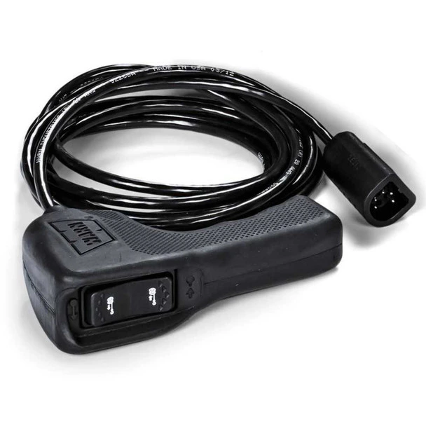 Wired remotes are the old-school setup you’ll see on work trucks and utility rigs. A cable runs from a connector on the bumper or control box to a small hand controller with IN/OUT buttons or a rocker switch. Inside that controller, there’s nothing fancy. Each button is just a momentary contact that ties the common wire to either the IN or the OUT signal wire going back to the solenoids. No electronics, no firmware, no pairing. Advantages:
- Very reliable. As long as the wires and plug are intact, it works. No RF dropouts, no pairing headaches.
- No batteries to worry about. It runs off the winch’s control circuit, so if the winch has power, the remote does too.
- Simple 3‑pin plug wiring or 4‑wire setup is easy to trace with a test light or meter on the trail.
- Usually the lowest cost option and often included with the winch from the factory.
- Range is only as long as the cable, typically 8–15 ft. Sometimes that puts you right where you’d rather not stand.
- The cord itself can get pinched, cut, or snagged in doors, under tires, or around rocks and branches.
- You’re tied to the front of the truck. In deep mud or sketchy recoveries, that can mean standing in the splash zone or in line with the cable.
Wireless Winch Remotes
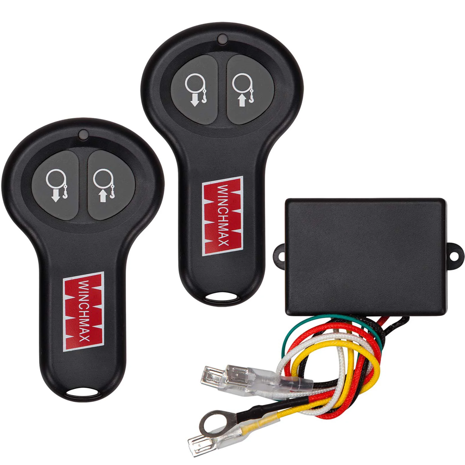 Wireless remotes add a small wireless receiver into the control box and pair it to a handheld RF transmitter, most often on the 433MHz band. Premium setups use coded or rolling signals and better RF front ends to ignore noise. In practice, a good wireless system lets you walk way off to the side, watch your line angle, watch the anchor, and winch without juggling a dangling cord. Advantages:
- Extended range. Many decent systems give 50–100+ ft line-of-sight, which is plenty for off-road recoveries.
- You can stand in safer positions, off to the side of the cable and away from the potential snap-back zone.
- No cord to drag through mud or wrap around a tire. Less junk to step on in the dark.
- They depend on batteries. A dead fob battery has stranded more than a few people. Always carry spares.
- Can be affected by RF interference from other devices, big metal bodies, or bad antenna placement.
- Cheap receivers with vented or unsealed cases suck in water and fail. If the kit isn’t properly sealed, it won’t last long off-road.
Wired vs Wireless Winch Remotes: Comparison Table
Here’s a side-by-side look to help you pick what fits your build. Think about how you actually wheel, not just what looks cool.| Feature | Wired Remote | Wireless Remote |
|---|---|---|
| Typical Cost | Low (often included, $20–$60 to replace) | Medium–High ($40–$200+ depending on brand/features) |
| Range | Cable length (8–15 ft typical) | 50–100+ ft line-of-sight (depends on 433MHz module and antenna) |
| Durability | Excellent if cable and plug are protected | Good to excellent; depends on IP rating and housing |
| Interference Risk | None (hard-wired) | Possible RF interference, pairing loss |
| Power Source | Uses winch control circuit power | Hand remote uses internal batteries; receiver uses winch power |
| Installation Complexity | Simple plug/cable; 3‑pin or 4‑wire remote | Requires wiring wireless receiver into solenoid |
| Best Use Case | Budget builds, work trucks, maximum reliability | Off-road recovery, solo winching, remote operation |
Wiring a Winch Remote: 3‑Pin, 4‑Pin & Wireless Diagrams
 Under the cover, almost every winch remote is just a low-current control circuit. You have one common reference wire, then separate IN and OUT signal wires going to the solenoid pack. Here we’ll look at a typical 3‑pin remote connector, a 4‑wire remote, and how a wireless receiver ties into the same control points without hacking the whole harness apart.
3‑Pin Wired Remote Wiring (Diagram)
The 3‑pin plug is what you’ll see on a lot of truck and ATV winches. Three small wires run from the controller socket into the solenoid pack. Those are your common, IN, and OUT lines. Typical 3‑Pin Functions:- Pin 1: Common (often 12V+, but some winches use ground as common)
- Pin 2: IN signal (triggers the “winch in” solenoid coil)
- Pin 3: OUT signal (triggers the “winch out” solenoid coil)
- Connector type: A Deutsch 3‑pin connector or similar waterproof automotive connector is ideal. Cheap open plastic plugs corrode and fill with mud.
- Voltage rating: Usually 12V or 24V depending on your winch system.
- Current capacity: Control wires only need a few amps to energize relay or solenoid coils, but good connectors are often rated 10–15A to give you margin.
- Waterproof seal: Shoot for at least IP67 rating so it survives dunking and repeated mud baths.
- Red – Common 12V+
- Green – IN signal
- Black – OUT signal
- Battery → big winch power cables → Solenoid pack.
- Solenoid/control box: three small control wires → 3‑pin plug on the bumper or control housing.
- Remote: matching 3‑pin cable → IN and OUT buttons → back to common line inside the controller.
4‑Wire Remote Wiring (Diagram)
Some winches run a 4‑wire remote. You’ll see this when they want a dedicated ground, an LED, a master power switch, or extra safety logic. Common 4‑wire functions can be:- 12V+ feed to the remote
- Ground
- IN signal return
- OUT signal return
- Red – 12V+ feed to the remote
- Black – ground
- Green – IN output back to solenoid coil
- White – OUT output back to solenoid coil
- Battery → fuse (1–3A) → 12V+ feed into the remote harness.
- Remote: 12V+ passes through a master toggle, then the momentary IN and OUT switches send that 12V+ back out on their respective lines.
- Remote ground ties into the common ground in the control box.
- IN and OUT wires land on the matching solenoid coil terminals.
Wireless Receiver Wiring
To convert a wired winch to wireless, you bolt in a small wireless receiver that copies what the wired remote does. It ties into the same common, IN, and OUT control lines at the solenoid pack. Basic wireless receiver wiring steps:- Power: Hook the receiver’s +12V (or +24V) and ground to the winch control box feed. Many kits show you exactly which posts to use.
- IN output: The receiver’s “IN” relay output connects to the winch’s IN control terminal.
- OUT output: The receiver’s “OUT” relay output connects to the OUT control terminal.
- Common: The receiver’s COM ties into the same common that the wired remote uses, whether that’s 12V+ or ground.
How to Wire a Remote Relay: Step‑by‑Step Diagram
A relay lets one circuit control another. On winch systems, we drop a relay in the control side, not the motor side. That’s how you add safety interlocks, ignition-only power, or a dash rocker that can’t be bumped accidentally with the key off. Here’s how to wire a 5‑pin relay module into your control circuit correctly instead of guessing and hoping you chose the right pin.5‑Pin Relay Wiring
A standard automotive 5‑pin relay is labeled 85, 86, 30, 87, and 87a. Two pins are the coil (85/86). The other three are the switching contacts (30/87/87a). Key Attributes (EAV entity: 5‑pin relay module):- Coil voltage: 12V DC for most vehicle and 4×4 work.
- Contact configuration: Usually SPDT (Single Pole Double Throw). One input, two possible outputs.
- Contact current rating: 20–40A typical. That’s plenty for control circuits, but not for running a winch motor directly.
- Mounting type: Often a plug-in base or inline socket you can clip to a panel or fuse block.
- Coil side (85/86):
- Terminal 85: Ground.
- Terminal 86: Your control signal. For example, ignition switched 12V or a small dash toggle.
- Contact side (30/87/87a):
- Terminal 30: Common input, usually the remote common wire or its 12V+ feed.
- Terminal 87: Normally Open (NO) contact that closes to 30 when the coil energizes.
- Terminal 87a: Normally Closed (NC) contact that is connected to 30 when the relay is at rest.
- Wire 30 to the remote’s 12V+ feed source.
- Wire 87 to the original point where that 12V+ fed the remote/common line.
- Feed coil 86 from an ignition-on circuit through a 1–3A fuse, and run coil 85 to ground.
- Result: the remote only gets power with the key on and the relay energized. No key, no winch.
NC vs NO Contact Explained
Whether you use Normally Closed (NC) or Normally Open (NO) contacts decides what the winch can do when the relay is just sitting there at rest.- NO (Normally Open): 30 and 87 are disconnected at rest. They only connect once the relay coil is energized.
- NC (Normally Closed): 30 and 87a are connected at rest. They open when the coil energizes.
How to Test and Bypass a Winch Without the Remote
Remotes get lost, soaked, or broken. If you’re stuck somewhere or just troubleshooting in the shop, you can still run the winch by bypassing the remote circuit at the solenoid pack. This is powerful and dangerous at the same time. Treat it like working under a car supported by a jack. You do it slowly, carefully, and only as long as you absolutely need.Safety First
- Wear heavy gloves and eye protection. A stray wire arc or a jumping hook is no joke.
- Chock the wheels and set the parking brake. Don’t rely on Park alone.
- Keep hands, jackets, and tools well clear of the winch drum and cable.
- Use short taps only. Touch, observe, and pull back. Never hold a bypass wire on continuously.
- If you’re unsure about any step, stop and get help from someone who does this work regularly.
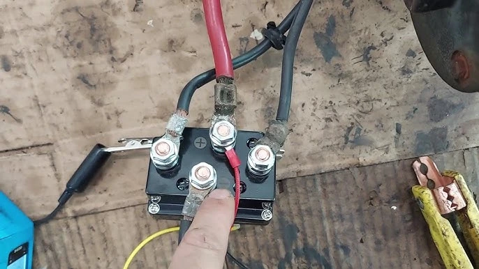
Solenoid Bypass Method
Here you’re imitating what the remote does. You briefly connect the common control wire to the IN or OUT terminal at the solenoid pack using a short jumper or a momentary switch. Steps (generic 3‑wire control):- Find the three small control terminals on the solenoid labeled or documented as common, IN, and OUT. If they’re not labeled, grab the manual or wiring diagram first.
- Use a short, insulated wire or a momentary push-button:
- Touch common to IN to get “winch in”.
- Touch common to OUT to get “winch out”.
- Tap very briefly to see if the motor responds. As soon as you know which direction works, stop and reassess what you’re doing.
Direct Battery Test
If you suspect the solenoid or motor is dead, you can go a step deeper. Here you feed the solenoid coil directly from the battery through a fused jumper. This is not for casual playing around. Basic outline:- Make sure the battery is healthy and all main winch cables are tight and clean.
- Identify the solenoid coil terminals or the control IN/OUT posts, depending on how your winch is built.
- Use a fused jumper wire (10–20A inline fuse) to go from battery positive to the coil terminal you want to test, with the other side of that coil grounded properly.
- Tap it. Hear a solid click and see or hear the motor run if the mechanical side is good.
DIY Winch Remote: Parts List, Schematic & Build Steps
If you’re handy with electronics, a custom remote lets you set up the exact range, layout, and safety features you want. You can even share one handheld for multiple rigs with matching receivers. Here’s a high-level plan for an Arduino Nano DIY wireless winch remote built around a 433MHz relay module. Treat this as a solid starting point, not a toy project. A mistake here can move a vehicle when no one expects it.Parts Needed
Core electronics:- Arduino Nano DIY board or similar 5V microcontroller to handle encoding, safety logic, and button reading.
- Wireless RF module (433MHz) transmitter and receiver pair rated for decent outdoor range.
- 433MHz relay module or a small two-channel relay board controlled by the Arduino or coded receiver.
- Operating frequency: 433MHz, which is a common license-free band used for key fobs and remotes.
- Transmit range: Around 100–300 ft line-of-sight with a proper antenna and clean power.
- Power supply: Most logic runs on 3.3–5V. Relay outputs may need 12V drive, so check the module specs.
- Interference immunity: Cheap bare-bones modules are sensitive to noise. Better boards use encoding and basic error checking to ignore junk signals.
- Two rugged momentary switches for IN and OUT on the handheld unit, rated for outdoor use.
- An optional master toggle switch or slide switch so you can arm/disarm the remote in your pocket.
- Good quality signal wire cable (18–22 AWG) for the control side wiring.
- A tough waterproof remote housing with a gasketed lid or O-ring seal.
- A waterproof automotive connector such as a Deutsch plug at the winch side so you can unplug or service easily.
- Gauge: 18–22 AWG is fine for low-current control lines.
- Insulation type: PVC is common. Silicone-insulated wire stays flexible in cold weather and holds up better to vibration.
- Voltage rating: 300V or so, which is far above what a 12V system needs but standard for automotive wire.
- Color coding standard: Stick with a sensible scheme like red for 12V+, black for ground, and green/white for IN/OUT, or clearly label whatever you choose.
Wiring the Circuit
Transmitter side (handheld remote):- Power the Arduino Nano from a small Li‑ion pack or a 9V through a proper regulator and protection board.
- Wire the IN and OUT buttons to Nano digital inputs with either internal or external pull-downs so they read cleanly when not pressed.
- Have the Arduino encode the command (IN or OUT, maybe with a rolling code) and drive the 433MHz transmitter module with that signal.
- Feed the 433MHz receiver into the Arduino Nano or a dedicated coded receiver that talks directly to a 433MHz relay module.
- The Arduino decodes the signal and energizes the appropriate relay for IN or OUT. Build in a timeout so it can’t latch on forever.
- Relay 1 NO contact goes between the common control line and the IN terminal on the solenoid.
- Relay 2 NO contact goes between the common control line and the OUT terminal.
- Power the receiver and relay board from the vehicle’s 12V through a small fuse (1–5A is plenty).
Weatherproofing
Winches live in about the worst place on a truck. They see water, mud, salt, heat, and constant vibration. Weatherproofing your DIY remote is not optional if you actually plan to use it. Waterproof remote housing attributes (EAV entity):- Material: Polycarbonate or rubberized plastic cases handle impact and UV without cracking quickly.
- IP rating: Look for IP67 or IP68 if you expect submersion, not just rain.
- Seal method: Screw-down lid with a molded gasket. Relying only on silicone goop usually fails after a season.
- Battery access: Design the case so you can swap batteries without tearing the seal or stripping screws every time.
- Use a remote boot seal or silicone rubber boots over the buttons so water can’t work its way down the switch shafts.
- Coat exposed board surfaces with conformal coating or fill dead spaces around electronics with potting compound to slow down condensation damage.
- Run the antenna away from the winch motor and battery cables. That improves wired vs wireless range performance and keeps the RF side cleaner.
How to Use Your Winch Without the Remote Controller
A lot of us build in a backup control method from the start. That way a lost or drowned remote doesn’t end the trip. These setups mimic the handheld remote using fixed switches or dash Best Winch Remote Controls of 2026 wired into the same IN/OUT circuits. These are simple on/off setups, not fancy variable-speed controls. Your fingers are the “feathering” system, so use short bumps and pay attention.Direct Solenoid Engagement with Switches
One common option is a small sealed switch box mounted near the winch or under the hood.- Run a fused 12V+ feed into the box from the battery or from the winch control power source.
- Inside, wire two momentary switches so they each feed 12V+ to the IN and OUT control wires when pressed.
- Share a clean ground reference with the winch control box so the solenoids see exactly what they expect.
Dash or On-Board Rocker Switch Installation
Many off-road rigs run a dash-mounted rocker switch or 3‑position momentary rocker (IN–OFF–OUT). That lets you operate the winch from the driver’s seat when you’ve got a good view or a spotter.- Use a center-off, momentary rocker that’s clearly labeled and rated for low-current control duty.
- Feed the rocker from a fused 12V+ source that’s only live with ignition on, or run it through that relay interlock we talked about earlier.
- Wire the rocker’s outputs to the IN and OUT control terminals just like a normal remote would be wired.
Safety and Limitations
- You still need to stand, or park, where you can clearly see the cable, fairlead, and anchor. Never just “feel it out” blind.
- If the switch is inside the cab, treat the winch like a loaded weapon. Use a spotter outside whenever you can, and keep comms clear.
- There is no proportional control here. The cable is either moving or it’s not, so pulse the switch instead of holding it.
Common Mistakes When Working with Winch Remotes (and How to Fix Them)
- Mistake 1: Assuming all 3‑pin remote wiring is identical. Fix: Don’t trust wire color alone. Verify common/IN/OUT with your manual or a meter. Some winches use ground as common, others use 12V+, and mixing that up can pop fuses or worse.
- Mistake 2: Running remote cables near exhaust or sharp edges. Fix: Reroute cables along existing factory looms. Use split loom, rubber grommets, and cushioned clamps, and keep them away from hot pipes and steering gear.
- Mistake 3: Using low-quality, non-sealed connectors. Fix: Upgrade to a Deutsch 3‑pin connector or another proper waterproof automotive connector with an IP67 seal.
- Mistake 4: Bypassing the solenoid for regular use. Fix: Use solenoid bypassing only for tests. For routine operation, install permanent switches, a dash control, or a reputable wireless kit.
- Mistake 5: Overloading relay contacts by switching motor current. Fix: Keep your relays on the low-current control side. The motor stays on the heavy winch solenoid pack. Don’t try to cheap out around that.
- Mistake 6: Ignoring corrosion inside the remote housing. Fix: On serviceable remotes, open them once in a while. Look for green crust, moisture, or cracked boots. Clean contacts, re-grease seals, and replace worn gaskets before they strand you.
FAQ: Winch Remote Controls
Here are straight answers to the questions I hear most often about winch remotes, wiring diagrams, and troubleshooting.How do I wire a winch remote?
To wire a winch remote, first identify the common, IN, and OUT control terminals on your solenoid pack. Then connect your remote’s three (or four) wires to those points following the manufacturer’s winch remote wiring diagram and color code. Always put a small fuse on any 12V feed going into the remote circuit.What is winch remote 3‑pin wiring?
Winch remote 3‑pin wiring uses three conductors in the plug: a common line, an IN signal, and an OUT signal. The hand controller has momentary switches that tie common to either IN or OUT while you hold the button, which energizes the matching solenoid coil and makes the winch spool in or out.How do I test a winch without the remote?
To test a winch without the remote, perform a solenoid bypass test. Briefly jump the common control wire to the IN or OUT terminal at the solenoid with an insulated jumper or momentary switch. If you’re checking the solenoids themselves, you can also use a fused jumper from the battery positive to each solenoid coil terminal, with the other side grounded. Tap only, and follow strict safety rules.Are wireless winch remotes reliable?
Quality wireless remotes from Warn, Smittybilt, and Superwinch are very reliable if installed by the book, with good waterproofing and smart antenna placement. The trouble starts with the no-name bargain kits that use thin housings, poor seals, and unfiltered receivers, which are more prone to RF interference and water damage.What’s better, wired or wireless winch remote?
For raw reliability and simplicity, a wired remote wins. There’s less to go wrong. For day-to-day convenience and the ability to stand clear of the danger zone, a wireless remote is excellent. Many off-roaders run both so they can use wireless most of the time and fall back on wired if something acts up.Can I build my own DIY winch remote?
Yes. A DIY winch remote using an Arduino Nano, a 433MHz RF module, and a relay board is very doable. Just remember you’re building a safety-critical control. It has to be fused, coded properly, and thoroughly weatherproofed, and it must fail in a safe way if anything glitches.How do I read a winch remote wiring diagram?
A typical winch remote wiring diagram shows the battery, solenoid, winch motor, and the low-current control circuit. Look for the common control line and the two signal lines labeled IN and OUT. Then trace how the remote switches or wireless relays connect that common line to the IN or OUT coils when you press the buttons.Why does my winch remote only work one way?
If the remote only runs IN or only runs OUT, you likely have a broken conductor in the cable, a bad button, corrosion in the plug, or a failed solenoid coil in that direction. Use a meter to check continuity from the remote to the solenoid terminal, then try a solenoid bypass at the pack to see whether the issue is in the remote or the winch.What range should I expect from a wireless winch remote?
Most 433MHz remotes advertise 100–300 ft line-of-sight, but in real-world conditions with a metal truck and trees around, 50–100 ft is more realistic. Mount the receiver high and away from big steel masses when you can, and use an external antenna if the kit supports it.Can RF interference trigger my winch by itself?
On a well-designed coded system, that’s very unlikely. The receiver looks for a specific pattern before it moves the winch. On very cheap or unfiltered receivers though, strong RF noise might cause weird behavior. That’s why you pick decent kits, wire them correctly, and use any master switch or key-based lockout when the winch isn’t actively being used.Final Summary & Next Steps
Your winch is only as trustworthy as the way you control it. Whether you stick with a tough wired remote, bolt on a proven wireless kit, or build a DIY Arduino-based remote, the fundamentals don’t change: clean wiring, correct fusing, proper connectors, real waterproofing, and a solid understanding of that common/IN/OUT control circuit. If you’re starting a fresh install or cleaning up someone else’s mess, begin by mapping your existing 3‑pin or 4‑wire layout. Choose sealed connectors and IP-rated housings, decide if you want wired, wireless, or a hybrid setup, and then plan your cable routing before you crimp the first terminal. Do it right one time and your winch remote will be ready to work every single time you reach for it, instead of letting you down when you’re buried to the frame rails.Step-by-Step: How to Wire a Basic 3‑Pin Winch Remote
- Disconnect power: Pull the negative battery terminal before you touch any winch wiring. That prevents accidental spooling if a wire brushes the wrong post.
- Access control box: Open the winch control or solenoid box and locate the three control terminals labeled or documented as common, IN, and OUT in your manual.
- Prepare cable: Cut a length of 18–20 AWG signal wire cable with three conductors in clear colours, for example red, green, and black, and strip the ends cleanly.
- Wire the connector: Crimp the proper terminals onto each wire and click them into your 3‑pin remote connector or other waterproof automotive connector. Use a consistent order like Pin 1 common, Pin 2 IN, Pin 3 OUT, and record it somewhere.
- Connect to solenoid: Land the other ends of those three wires on the matching solenoid control posts for common, IN, and OUT. Tighten the screws or nuts and give each wire a light tug to confirm it’s secure.
- Install plug mount: Mount the panel or bumper socket where it’s easy to reach but protected from direct rock hits. Route the harness through loom along existing wiring, away from heat, pinch points, and moving parts.
- Reconnect battery & test: Reconnect the battery, plug in the remote, and test IN and OUT in short bursts with no load on the cable. Watch the drum direction to confirm you didn’t swap the IN/OUT pins, and fix if needed.
Part of the Winch Accessories guide. Explore more guides in this cluster for complete coverage.
🔧 Why I Keep Two Remotes In The Rig
Tested remote failure scenarios on the bench: wired pendant cable crush-damaged by trail debris cost ~$45 to replace. Wireless fob battery died mid-trail — no signal, winch stuck. Now I keep both in the rig: wired pendant as primary, wireless as convenience. Swapped cables on three winches over the years using 16-gauge 5-conductor trailer wire and Deutsch DT series connectors — 30-min fix. Don’t trust a single remote as your only control path.